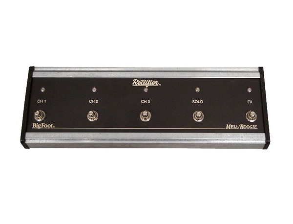
Bigfoot is a foot controller used for Dual & Triple Rectifier Head. It uses a non-standard and undocumented interface exposed on 8 pin DIN 270° connector so we need to reverse enginner it.

By disassembling it we can found the name of the pins printed on top of the PCB. After that, with a multimeter, we can observe the signal on that pins.
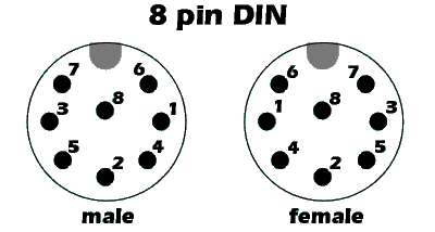
- PIN 1 is the GND
- PIN 2 is the Vcc 5V
- PIN 8 is disconnected
- PIN 6, called CH0 is unknown
- PIN 3 is called V-CH is the only one pin that controls the three channels of the Amps. V-CH at 0,7V meaning CH1 (Channel 1) selected, 1,25V meaning CH2, 1,90V meaning CH3
- PIN 4 SWB- and PIN 7 SWB+ are connected together and it controls the FX bypass switch. 0V means FX bypass OFF, 5V means FX bypass ON
- PIN 5 is called SWA and rules the SOLO switch. This pin is 0V when the SOLO gain is ON, and 5V when the SOLO is OFF
Now we can build a simple interface to emulate the pedal board:
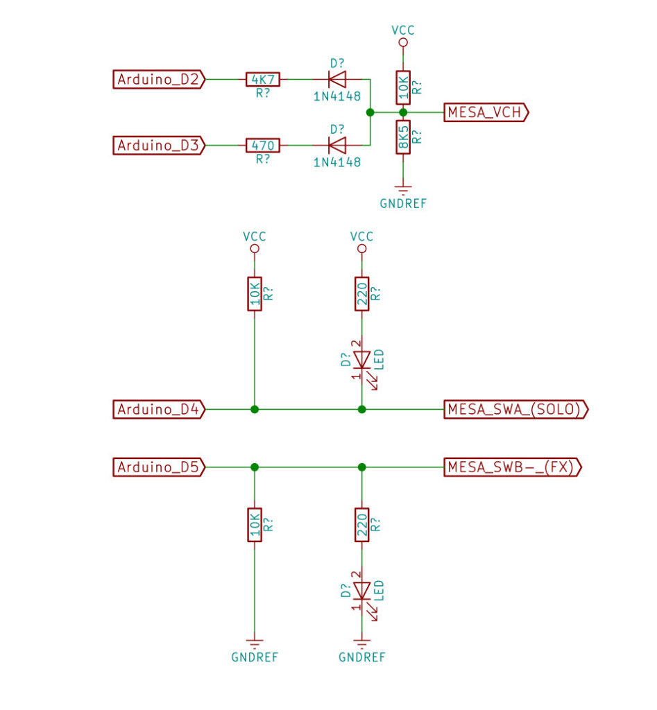
Where you see “Arduino” you can use any board that provides some digital outputs. These are the truth tables:
| SOLO GAIN | |||
|---|---|---|---|
| INPUT D4 | OUTPUT | LED | MEANS |
| 0 | 0 | ON | SOLO gain is ON |
| 1 | 1 | OFF | SOLO gain is OFF |
| FX Bypass | |||
|---|---|---|---|
| INPUT D5 | OUTPUT | LED | MEANS |
| 0 | 0 | OFF | FX bypass is OFF, so FX chain is active |
| 1 | 1 | ON | FX bypass is ON, so FX chain is disabled |
| CHANNEL SELECT | |||
|---|---|---|---|
| INPUT D2 | INPUT D3 | OUTPUT | MEANS |
| 1 | 1 | 1.90V | Channel 3 is selected |
| 1 | 0 | 1.25V | Channel 2 is selected |
| 0 | 1 | 0.70V | Channel 1 is selected |
| 0 | 0 | – | – |
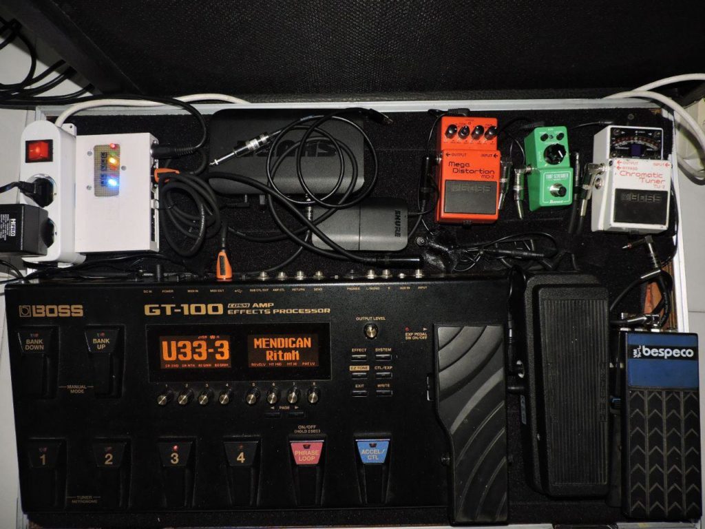
If you want to build a fully working BigFoot MIDI emulator, I’ve developed an open source device based on Arduino: HappySwitch – Open Source MIDI Amp Controller
