Decoding Oregon Scientific RTGN129 with RTL-SDR [PART 1]

Oregon Scientific RTGN129 is a remote temperature and humidity sensor designed to be used with Oregon’s PRYSMA series stations.
It uses the standard 433MHz band so we can tune our RTL-SDR USB dongle to receive their signal. But how to decode it?

There are plenty of documentation about decoding Oregon’s devices, and Benjamin Larsson’s rtl_433 tool may decode many of 433.92MHz devices but, unfortunately, it didn’t support the RTGN129.

This is the great opportunity to skill myself in reverse-engineering of an “unknown” signal, so I decided to implement it into rtl_433 (Merged pull request: https://github.com/merbanan/rtl_433/pull/634).

From RTGN129 datasheet we have the confirmation that this device transmits at 433MHz.

Oregon uses several protocol versions (v1.0, v2.1, v3.0) so, first of all, we need to discover if our RTGN129 uses one of these. Protocol documentation are here and here.

Instead of using directly rtl_433 in analyze mode (-a flag), we’ll pretend it does not exist and we’ll go down to low level just for fun. A sort of simulated black-box approach.

There are several tools in the wild to analyze the radio signal from an RTL dongle, but one of the best, IMHO, is baudline.

You can use it in the “hacker’s way”, for example:

FR="433.944e6"; SR="2.5e6"; \
rtl_fm -f $FR -s $SR -g 30 -M am | \
baudline -reset -flipcomplex -samplerate $SR \
-basefrequency $FR -channels 2 -quadrature \
-format u8 -fftsize 2048 -stdin

First of all, we need to find the right PPM value to use in the next commands to calibrate our dongle.

rtl_test -p

So we can find the exact frequency of RTGN129 starting from the 433.92MHz:

FR="433.92e6"; SR="2.5e6"; \
rtl_sdr -p 130 -f $FR -s $SR -g 30 - | \
baudline -reset -flipcomplex -samplerate $SR \
-basefrequency $FR -channels 2 -quadrature \
-format u8 -fftsize 2048 -stdin

Where -p is our PPM, -f is the tuned frequency, -s is the sample rate, and -g is the gain (0 for auto). The last “-” before the pipe stands for “stdout”.
433.92e6 stands for 433.92 * 10^6 so 433.92MHz that is more readable than 433920000.

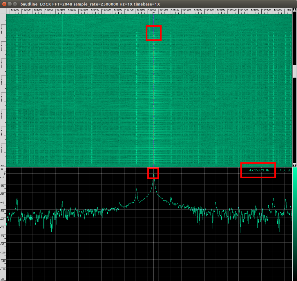
The above command shows you the baudline window. When you see the burst passing in the spectrogram press “pause” on your keyboard, center the signal in the spectrogram area (green background) with the mouse, than center it in the spectrum analyzer (black background) and read the exact frequency on the bottom-right area: 433.95Mhz

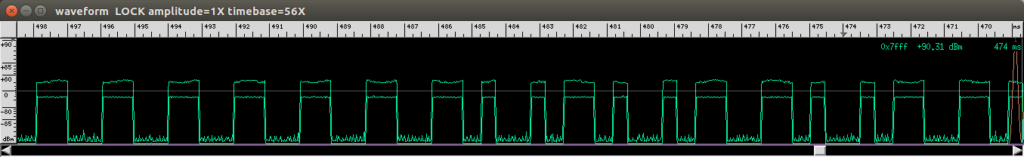
Right click on the spectrogram area, then select display, then click wafeform. Now we can see the waveform of the signal in the time domain. To zoom in/out you may use ALT + right and left arrows.

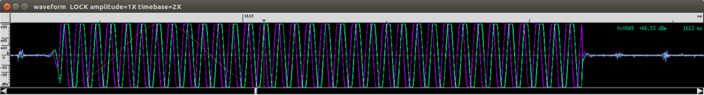
Navigating the waveform we notice that, when the signal is present, the frequency and the amplitude stills the same, and there are silence between two signal, just like in the On-Off Keying!

Basic digital modulation formats:

Now we use “rtl_fm” instead of “rtl_sdr” to demodulate the signal using AM demodulator:

FR="433.95e6"; SR="2.5e6"; \
rtl_fm -f $FR -s $SR -g 30 -M am | \
baudline -reset -flipcomplex -samplerate $SR \
-basefrequency $FR -channels 2 -quadrature \
-format u8 -fftsize 2048 -stdin

and finally visualize the demodulated bits!

If we decode it as “Manchester code” we read:

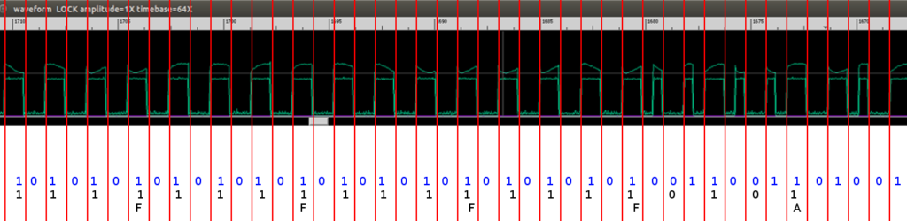
Instead of frustrating us overlaying red lines in gimp, as I did with the above image, we can use Universal Radio Hacker to decode the stream!

(to be continued …)

Restauro di un misterioso Zeiss Tessar del 1953

L’anno scorso acquistai uno Zeiss Tessar 50mm f/2.8 da riparare rispondendo ad un annuncio su un gruppo Facebook.
La particolarità di questo esemplare è che è marchiato “Ernst Abbe Jena” e non “Carl Zeiss Jena” e si presenta con le scritte dorate invece che bianche.
Avevo già letto di un esemplare simile su un articolo di Pierpaolo Ghisetti, nel sito di Marco Cavina, che cito testualmente:

“Una versione rarissima ed estremamente particolare di questo obiettivo è costituita dal Tessar f/2,8 marcato Ernst Abbe Jena. Questo Tessar presenta le scritte dorate e non bianche, la T, anch’essa dorata, e la doppia scala delle distanze.

Il significato dell’incisione dedicata ad Abbe (creatore della Fondazione Zeiss) risiede o nella commemorazione di un Giubileo, mai però chiarito, oppure in una prova di mercato per la sostituzione del marchio CZJ, in vista dell’azione legale della Carl Zeiss di Oberkochen, che rivendicava i diritti sui marchi Zeiss, Tessar compreso.

Pertanto si era pensato ad Abbe per creare un marchio alternativo: tuttavia il nome Zeiss era definitivamente affermato, mentre Abbe era conosciuto solo da pochi specialisti. In conseguenza l’iniziativa fu lasciata cadere, dopo poche decine di pezzi realizzati.”

Tuttavia il mio esemplare presenta una differenza rispetto a quello descritto da Pierpaolo Ghisetti, ovvero, non possiede la doppia scala delle distanze di messa a fuoco, ma solamente la scala metrica.

Poiché aveva l’elicoide bloccato decisi di aprirlo per capire il problema. Procedetti quindi a svitare l’anello sulla lente frontale, quello che presenta la scritta dorata “Enrst Abbe Jena”, e con mio stupore trovai un secondo anello, stavolta con la canonica scritta “Carl Zeiss Jena” in bianco, con la “T” rossa, ed un numero di serie diverso, come se fosse stato “rimarchiato”.

Il seriale riportato sull’anello “Ernst Abbe Jena” è “3805021”, mentre quello sull’anello sottostante è “3826545”.

Grazie all’aiuto di Pierpaolo Ghisetti che ha potuto consultare il FabrikatioBuch Zeiss (master di produzione), scoprimmo che entrambi i seriali si riferivano ad esemplari prodotti nel 1953 per “Exakta”, quindi innesto EXA e non a vite 42x1mm, ma ciò non è molto significativo in quanto spesso i lotti di produzione venivano stornati ove necessario col semplice cambio di zoccolo.

Pierpaolo conclude:

“I casi sono due: un falso incollato per aumentare l’appeal dell’ottica abbastanza comune, oppure un originale CZJ fatto artigianalmente e quindi non identico alla mini produzione. Diciamo che visto il caos produttivo in DDR può essere tutto.”

La tesi che sia un esemplare uscito da Zeiss con il doppio anello è supportata anche dal fatto che, confrontando il mio Tessar con quello fotografato da Pierpaolo nel 2011, si possono notare diversi particolari in comune:

  • La filettatura disponibile per il filtro è scarsa su entrambi, circa 2 spire
  • L’anello con la scritt Ernst Abbe ha i tagli per il giravite a compasso come il mio, gli anelli delle versioni classiche non li hanno
  • Il tronco di cono sottostante l’anello (non conosco la nomenclatura esatta) sembra essere diviso in 2 come nel mio esemplare, ed è così anche in quelli non “Ernst” in quanto la parte superiore del cono è un solo pezzo con l’anello riportante la scritta “Carl Zeiss Jena”

La mia tesi è che tutti, o quasi, i pochi modelli marchiati “Ernst Abbe Jena” potrebbero avere il doppio anello. Purtroppo l’esemplare fotografato nel 2011 da Pierpaolo non è più in suo possesso per poter verificare.

A seguire qualche immagine durante la fase di pulitura e nuova lubrificazione con grasso al litio.

Build a MESA/Boogie BigFoot emulator

Bigfoot is a foot controller used for Dual & Triple Rectifier Head. It uses a non-standard and undocumented interface exposed on 8 pin DIN 270° connector so we need to reverse enginner it.

By disassembling it we can found the name of the pins printed on top of the PCB. After that, with a multimeter, we can observe the signal on that pins.

  • PIN 1 is the GND
  • PIN 2 is the Vcc 5V
  • PIN 8 is disconnected
  • PIN 6, called CH0 is unknown
  • PIN 3 is called V-CH is the only one pin that controls the three channels of the Amps. V-CH at 0,7V meaning CH1 (Channel 1) selected, 1,25V meaning CH2, 1,90V meaning CH3
  • PIN 4 SWB- and PIN 7 SWB+ are connected together and it controls the FX bypass switch. 0V means FX bypass OFF, 5V means FX bypass ON
  • PIN 5 is called SWA and rules the SOLO switch. This pin is 0V when the SOLO gain is ON, and 5V when the SOLO is OFF

Now we can build a simple interface to emulate the pedal board:

Where you see “Arduino” you can use any board that provides some digital outputs. These are the truth tables:

SOLO GAIN
INPUT D4 OUTPUT LED MEANS
0 0 ON SOLO gain is ON
1 1 OFF SOLO gain is OFF
FX Bypass
INPUT D5 OUTPUT LED MEANS
0 0 OFF FX bypass is OFF, so FX chain is active
1 1 ON FX bypass is ON, so FX chain is disabled
CHANNEL SELECT
INPUT D2 INPUT D3 OUTPUT MEANS
1 1 1.90V Channel 3 is selected
1 0 1.25V Channel 2 is selected
0 1 0.70V Channel 1 is selected
0 0

If you want to build a fully working BigFoot MIDI emulator, I’ve developed an open source device based on Arduino: HappySwitch – Open Source MIDI Amp Controller

Carenar 50mm f/2.8 aperture control hack: Auto to Manual conversion

The Carenar 50mm f/2.8 with M42 screw mount was a cheap Japanese prime lens made by Cosina Co., Ltd. with a two blades iris.

Unlike other M42 lenses with automatic aperture control pin, this Carenar can’t be adapted by a ring that keeps the control pin pressed because the pin can be full pressed only if the aperture ring was set to f/16.

On the other hands, if the aperture ring was set to f/2.8, the pin cannot be pressed at all.

Some M42 lenses have an AUTO/MANUAL switch that leaves the pins free to move, but the Carenar 50mm f/2.8 doesn’t have that feature.

The mod consists of replacing the spring between the pin and the lever and unhooking another little spring.


This is the original mechanism. We need to unhook the spring “1” and replace the spring “2” with a larger one.


In the original mechanism the small spring hits the washer of the pin. The new spring needs to be larger than this washer so it can be fitted between the bottom of the barrel and the little lever.


We can get the new springs in a retractable pen.


We need to cut it.


And fitting between the bottom of the barrel and the lever using a little washer on the top of the spring.
If the mod works, the lever that moves the aperture blade is kept against the barrel walls by the new spring and not in the center of the barrel.