
This circuit needs to adapt a PWM/TTL laser module to a 3D printer using a cooling fan output.
You need to use a laser which has the PWM/TTL control on a port different from the one used for the power.
You can turn the laser ON with GCODE command M106 Sxxx (where xxx is an integer number from 0 and 255) and the laser OFF with M107
For example:
M106 S127 ; This line turns the laser ON to half power (50%)
M106 S255 ; This line turns the laser ON to full power (100%)
M107 ; This line turns the laser OFF
M106 S0 ; This line turns the laser OFF too (0%)
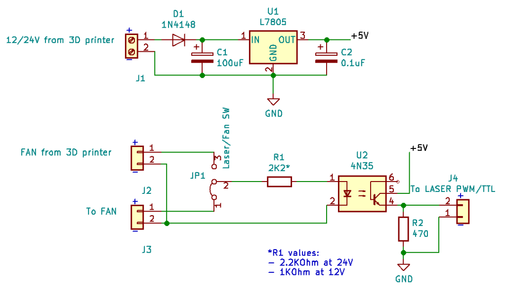
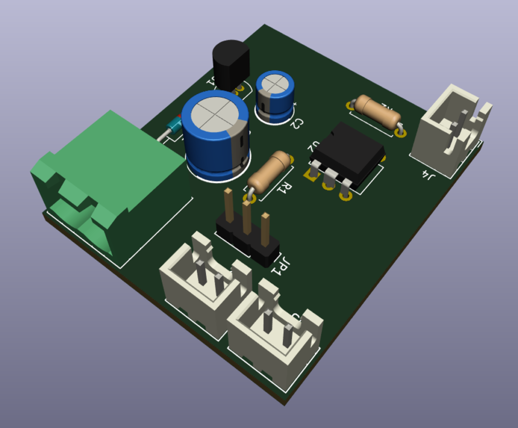
Through the use of JP1 jumper you can switch from Laser to Fan, so you don’t need to detach this interface to use your printer normally.
12V or 24V printer
If your FAN runs at 24V R1 must be 2.2KOhm, if it runs at 12V R1 must be 1.1KOhm.
Note that JST (white) connectors are rotated to respect Creality 3D Ender 3 PRO polarity, so if your printer has inverted polarity rotate the JST connectors accordingly.
GitHub Repository
https://github.com/siddolo/3Dprinter-laser

Thanks for the article, I only have one question, I bought a laser on ebay
(Link: https://www.ebay.com/itm/15WB-Laser-Head-Engraving-Module-with-TTL-450nm-Blu-ray-Wood-Marking-Cutting/293054392358?_trkparms=aid%3D555018%26algo % 3DPL.SIM% 26ao% 3D1% 26asc% 3D58646% 26meid% 3D63303e00c4c9416d8be7cb776ffb9830% 26pid% 3D100005% 26rk% 3D2% 26rkt% 3d12% 26mehot% 3Dag% 26sd% 3D323831859571% 26itm% 3D293054392358 & _trksid = p2047675.c100005.m1851 & fbclid = IwAR0uqq1YOZo8iZHsr8cHqr6CzSXeKM0qSeqPWGwtxsS6td-ZUCj2dxTXLpw )
As I know, you already have a module, is it necessary to integrate this adapter again or is it enough to place a 7812 regulator to decrease the amps?
Thanks in advance for your response.
I clarify that the printer is an Ender 3 Pro
Hi Hugo,
sorry for delay in the answer.
The Ender 3 PRO has a 24V power supply, but the laser module needs to be controlled by a 5V PWM signal, so yes, this module is necessary to dimmer the laser power between 0% and 100% power.
thanks a lot!!
If you want to use fan you need to connect 1 and 3 JP and if i wont pwn/ttl on 5v then 2 and 3 JP shud be short ?
yes, you’re right.
Hi- how to connect this module to ender 3 pro. thank you .5.5w high power 445NM focusing blue laser module laser engraving and cutting TTL module 5500mw laser tube+goggles
https://a.aliexpress.com/Dv6t4Z7w
Hi Marian:
– connect J4 of this board with a white JST connector of the laser (TTL 0-5)
– connect J2 to the FAN connector of ender 3 mainboard
– connect FAN to J3
Hi i dont understand the part of 7805 how i put all together
Thanks and sorry for my english
Hi Ricardo, the output of 7805 (+ 5V) must be connected to 5th PIN of 4N35 (+ 5V), and both GNDs are connected together. Please, take in mind that laser is DANGEROUS, you shouldn’t proceed if you’re not sure what you’re doing.
Hi I made your board but when i connect to power supply i get 2,54V and turns on laser with out any signal from ramps. Is that normal or I wired it wrong?
After 2 attemps i could not get this to work.
First time on a protoboard and the second time i directly copied your design and used Kicad to merge the groundings for a single layer PCB.
Any help would be much appreciated as my laser has only been good for making squiggly lines at the moment…
I am right in assuming this board will accept M106 S0-255 to set laser power? Love the idea of this and haven’t found anything elsewhere, just getting it to work is giving me a headache.
One last thing i forgot to mention i am using L7805 but in T220-3 form factor.
Hey im running it on an Ender 3 pro. 24v Mainboard 1.1.4. No other modifications.
After carefull assembly i’ve managed to get the board built but have now run into an issue.
I’ve managed to get the laser working fine with M106 commands but the “cooling fan output” is only putting out 0.1v max. All components have been checked and double checked resistance and diode polaritys, Checked voltage output from the….
Upon writing this i realise i have wired my switch/JumperPins incorrectly…. Everyone ensure you have JP1 wired correctly. If you are getting the wrong voltages…
Excellent board and good work sid!
From everyone building thank you!
If anyone can come up with a decent way to impliment a indicator LED please post your results.
What do you mean as “indicatore LED”?
hello I bought a neje laser whose pwm pin is controlled from 3.3 to 12v will this system allow me to control the laser power? the laser has 4 pins vcc gnd pwn and measuring the temperature which I will not use.I wanted to connect the system to the 24V ender 3
Hi,
I would like to use this laser which has a ttl as they say 3.3 at 12v can i use it without problems with your schematic?
https://it.aliexpress.com/item/1005001582474698.html?spm=a2g0s.9042311.0.0.78f14c4dhkBQMA
Thanks
If the laser can’t tolerate the 5V, you need to change the power supply (first part of the circuit) with a step-down to 3.3V and apply this voltage to 5th pin of U2 IC