L’app “Mastella” non ha nulla a che fare con l’Intelligenza artificiale e invia la posizione geografica all’insaputa dell’utente.

DISCLAIMER
Tutte le informazioni che troverete in questo post si basano su constatazioni oggettive, inconfutabili, e corredate di evidenza tecnica. Per questo motivo, alcuni passaggi possono risultare ostici ai non addetti ai lavori.
Chiunque, in qualsiasi momento, può verificarne la veridicità effettuando le stesse indagini in maniera indipendente.
La seguente analisi è perfettamente lecita e legale in quanto effettuata esclusivamente sul mio telefono e prende in esame l’applicazione “Mastella”, nella versione 6.32, scaricata dal Play Store ufficiale Android.
Anche le analisi riguardanti il traffico di rete sono state effettuate in modo passivo, ovvero osservando esclusivamente ciò che l’applicazione invia al suo server durante il normale utilizzo. Nessuna richiesta di rete è stata manipolata e/o inviata in maniera arbitraria al server. Ovviamente conservo il dump del traffico generato durante l’analisi a supporto delle mie affermazioni.
Insomma, per dirlo con un’altra parola stra-abusata a sproposito: non è stato “hackerato” niente.
L’APPLICAZIONE RICICLATA
Dillo a Clemente, distribuita sugli store Apple e Android con il nome Mastella è stata “sviluppata” da Analist Group s.r.l. di Avellino in Xamarin, una piattaforma di sviluppo mobile che consente di scrivere codice C# (C Sharp) che è un linguaggio di programmazione dell’ecosistema .NET di Microsoft.
Ho virgolettato “sviluppata” non a caso, perché sia l’app che il back-end (l’applicazione lato server con cui comunica l’app che gira sul vostro telefono) sono un’accozzaglia di codice proveniente da altre applicazioni e riutilizzate in malo modo.
Attenzione: seppure questa affermazione è sicuramente vera per la parte client (l’app appunto), non può essere verificata per quanto riguarda il back-end poiché il codice gira sul server e non è possibile “scaricarlo”. Ci sono però degli elementi che lo lasciano pensare.
L’applicazione riciclata per creare “Mastella” si chiama “Instanteat”, ovviamente sempre sviluppata da Analist Group, e la trovate sul Play Store e Apple Store.
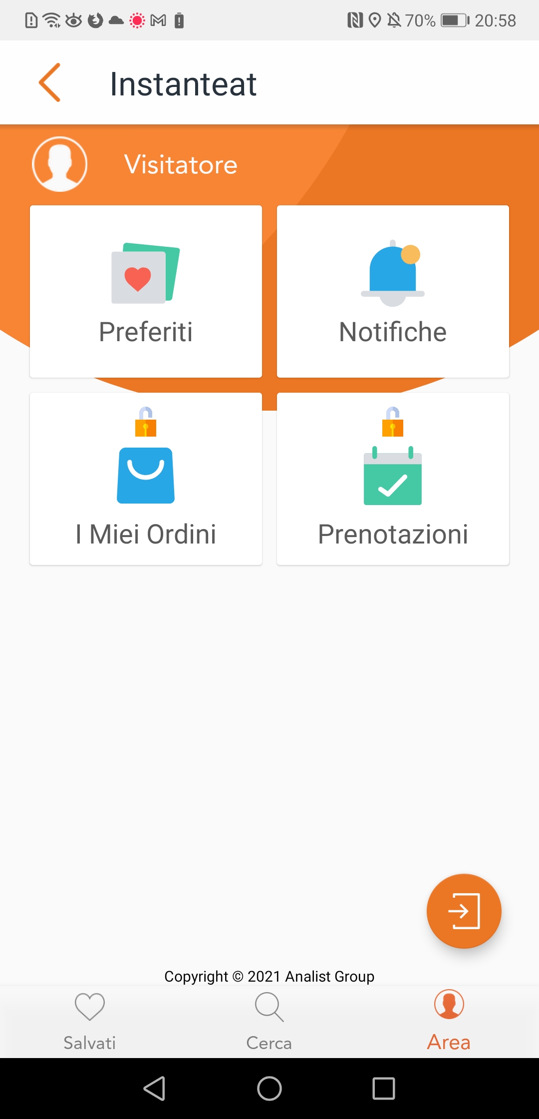
Provate a cliccare sull’icona in basso a destra dell’app “Mastella”, vi verrà fuori un menu che non ha molto a che fare con la funzionalità dell’app.
Qualcuno potrebbe obiettare che non si tratta di riciclo, ma della nobile arte di riutilizzo di codice tramite il medesimo framework applicativo. No, fidatevi, è roba riciclata e anche male.
A questo indirizzo trovate lo sfondo che l’applicazione Mastella carica all’avvio: https://instanteat.s3.eu-central-1.amazonaws.com/mastella/Media/User-1-281/BC_tblMenu/1/97693ed394464eda8d0578d543436a1a-SplashAPPMastellavertical.png
Il bucket S3 utilizzato da “Mastella” per memorizzare gli asset statici (le immagini ad esempio), è lo stesso di “Instanteat”: instanteat.s3.eu-central-1.amazonaws.com.
Non siete ancora convinti? Bene, il namespace dell’applicazione “Mastella” è proprio “Instanteat”, e il codice sorgente è compilato nel file col nome “Instanteat.dll”.
Imho, hanno clonato il repository dell’app Instanteat contenente l’intera solution (sono ottimista, non voglio pensare sia solo una banale cartella condivisa in rete), sostituito il nome da “Instanteat” a “Mastella”, il package name da “com.analistgroup.instanteat” a “com.analistgroup.mastella”, l’indirizzo del backend da “master.instanteat.it” a “mastella.mapservice.eu” più altre cosucce, disabilitato alcune voci di menu, buildato senza rimuovere il resto del codice inutilizzato, e pubblicato il tutto in fretta e furia per la presentazione in pompa magna durante la campagna elettorale.
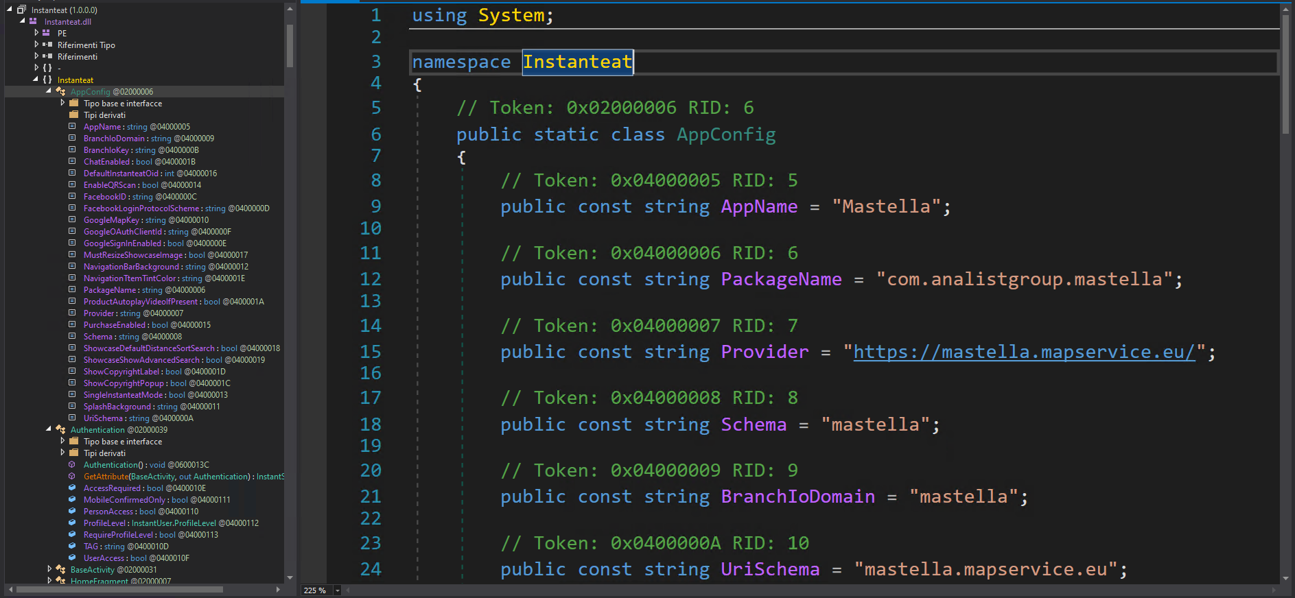

Se “Mastella” non ha lo scopo di prenotare il ristorante, “Instanteat.Agenda.Restaurant.Booking” non ha ragione d’essere, e se “Instanteat” voleva essere un framework, è ben lontano da esserlo.
Ma diamo un occhio anche alle risposte ritornate dal back-end alle nostre due app, fate caso all’header Access-Control-Allow-Origin che dovrebbe regolare il funzionamento delle CORS:


Alla fiera di .(dot)NET, per due soldi, un repository lo sviluppatore clonò […] E venne Mastella che clonò Instanteat, che clonò SanaLives, che per due soldi Analist Group sviluppò… (Si scherza eh… – NdR)
INTELLIGENZA FECALE
No, seriamente. Le parole “Intelligenza artificiale” sono usate a sproposito. Accade spesso tra i non addetti ai lavori, ma questo caso è eclatante.
Cosa fa l’app? Quali sono le sue funzionalità?
Tralasciamo pure il menu accessibile dall’icona in basso a destra, quella a forma di omino, che porta alla schermata con le icone “Preferiti”, “Notifiche”, “I Miei Ordini”, “Prenotazioni” (cosa, il ristorante? 🙂 ) Di queste cose non funziona niente, almeno ad oggi.
Cosa rimane? La schermata principale con l’icona del microfono con cui è possibile parlare con Clemente grazie all’intelligenza artificiale che capirà ciò che diciamo e ci risponderà in modo sensato. NO! NO! NO! NOOOO! CAZZO NO!
L’iconcina del microfono non fa altro che utilizzare una funzionalità di Google* (non di Mastella e non di Analist Group) che si chiama speech-to-text. Questa funzionalità già presente nei nostri smartphone (la stessa che usa l’assistente vocale quando dettiamo un messaggio, ad esempio) si occupa di trasformare quello che diciamo in testo. Fine.
*Sì, le funzionalità speech-to-text e text-to-speech di Google migliorano la propria precisione grazie anche al Machine-Learning. Ma questa è un’altra storia che non ha nulla a che vedere con l’app “Mastella”.
Dopo tale lavoro effettuato da una libreria di Google (nella versione Android dell’app), il testo generato da quest’ultima viene recuperato dall’app “Mastella” e inviata al back-end (server).
Il server controlla se il testo da noi inviato è presente tra quelli inseriti a mano dagli sviluppatori dell’app. Se lo è ci risponde con la risposta associata (anch’essa inserita a mano dagli sviluppatori), una supercazzola. Se la domanda da noi inviata non è presente o non è formulata nella maniera esatta a quella inserita dagli sviluppatori, l’app ci risponde che ha capito e ci farà sapere.
Le domande che possiamo fargli, quindi, sono limitate a quelle inserite nel server. Né l’applicazione, né il back-end hanno la capacità di “capire” quello che gli stiamo chiedendo.
Sul sito ufficiale, cliccando sul pulsante giallo “Cosa puoi chiedermi” parte un MP3 (sì, avete capito bene, un ormai vintage MP3) che ci “suggerisce” cosa possiamo chiedergli, ovvero le domande che gli sviluppatori (o lo staff) hanno inserito e a cui hanno associato una supercazz… ehm, una risposta: https://www.dilloaclemente.it/mp3/clemente-richiesta-3.mp3
Esempio: se chiediamo “Cosa hai fatto per la città?” (esattamente come ci indica il sito ufficiale), il server ci risponde con “Abbiamo risanato le casse del Comune, quelle delle due municipalizzate migliorandone anche i servizi e preservando il personale e abbiamo intercettato decine di milioni di euro di finanziamenti pubblici per trasformare la città e renderla più bella e accogliente. Senza dimenticare che abbiamo anche fronteggiato l’emergenza Pandemia senza lasciare mai nessuno da solo.“, tale testo sarà poi letto da un altro servizio google chiamato stavolta text-to-speech.

Bene, adesso provate a formulare la domanda in maniera leggermente diversa, esempio: “Cosa hai fatto per Benevento?” La risposta sarà un triste “Ho capito e ti farò sapere quanto prima”. Le faremo sapere, insomma.
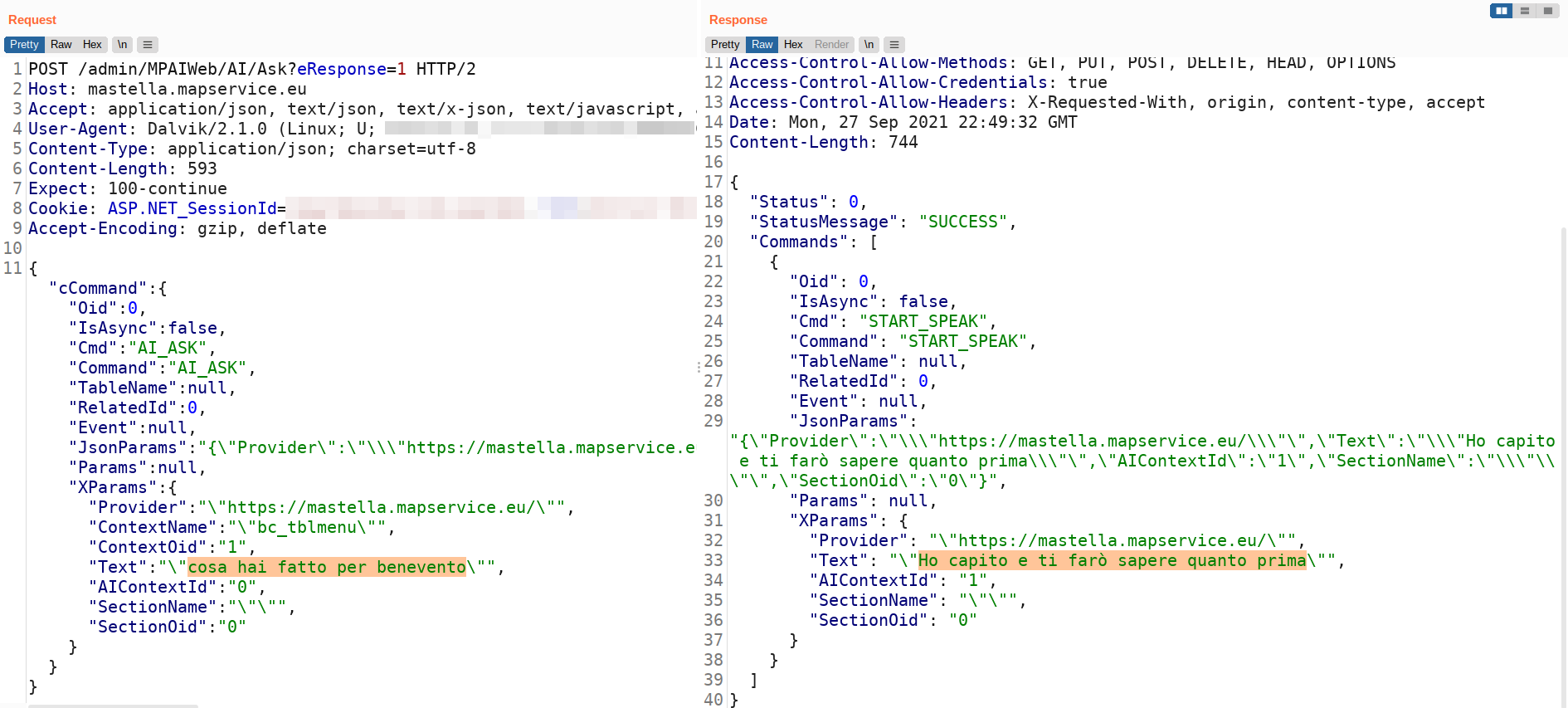
Dev’essere veramente molto stupida questa intelligenza artificiale. No! Non c’è alcuna intelligenza artificiale!
Semplicemente hanno associato alle parole “fatto per la città” quella risposta. Prima di quella sequenza potete dire qulasiasi altra cosa, vi risponderà sempre la solita supercazzola, ma se cambiate anche solo una parola della sequenza da loro cablata, non troverà alcuna risposta all’interno del database.
Indovinate cosa risponde a: “Supercalifragilistichespiralidoso, anche se a sentirlo può sembrare spaventoso, se lo dici forte avrai un successo strepitoso, fatto per la città“?

GEOLOCALIZZAZIONE
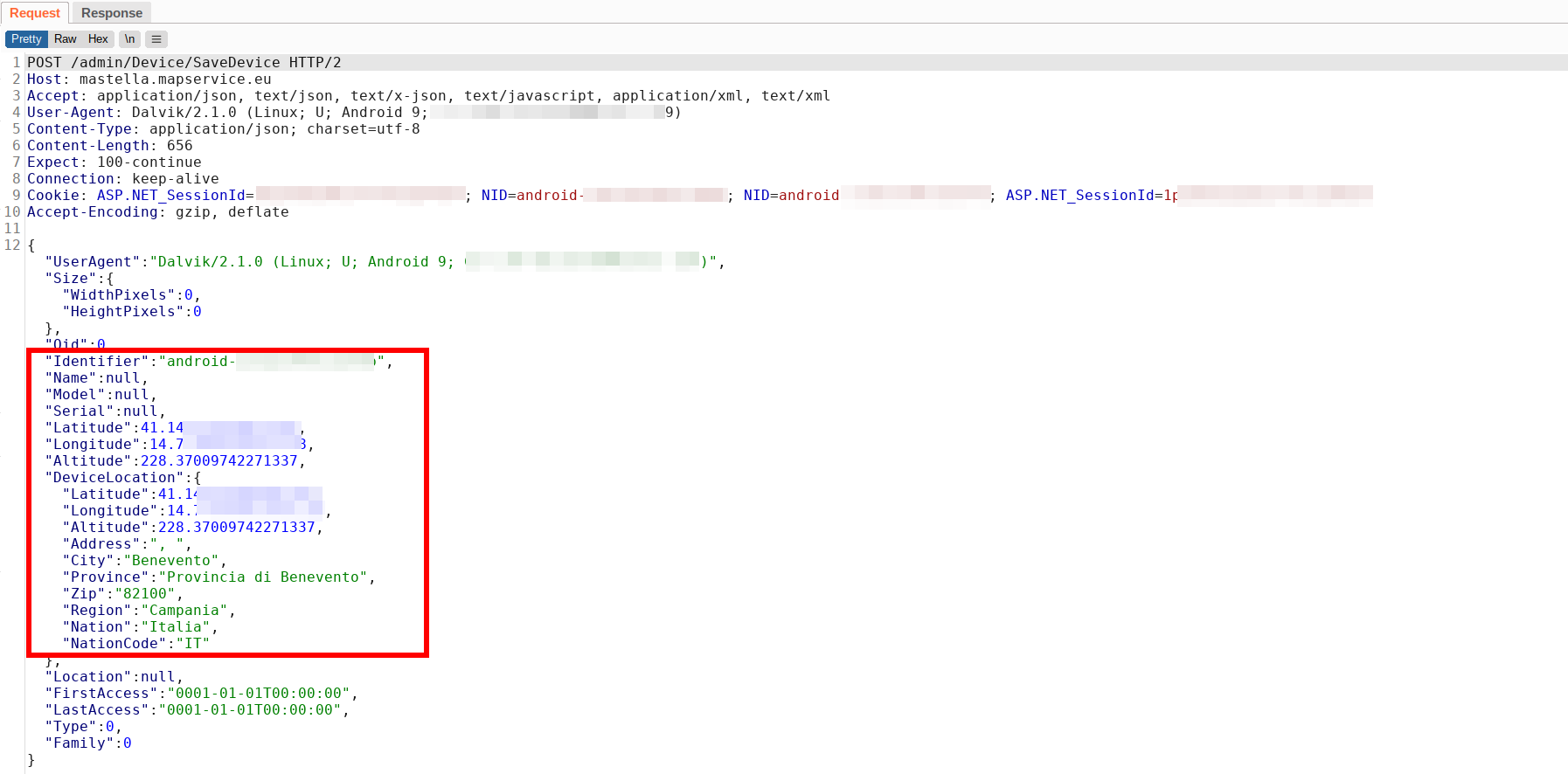
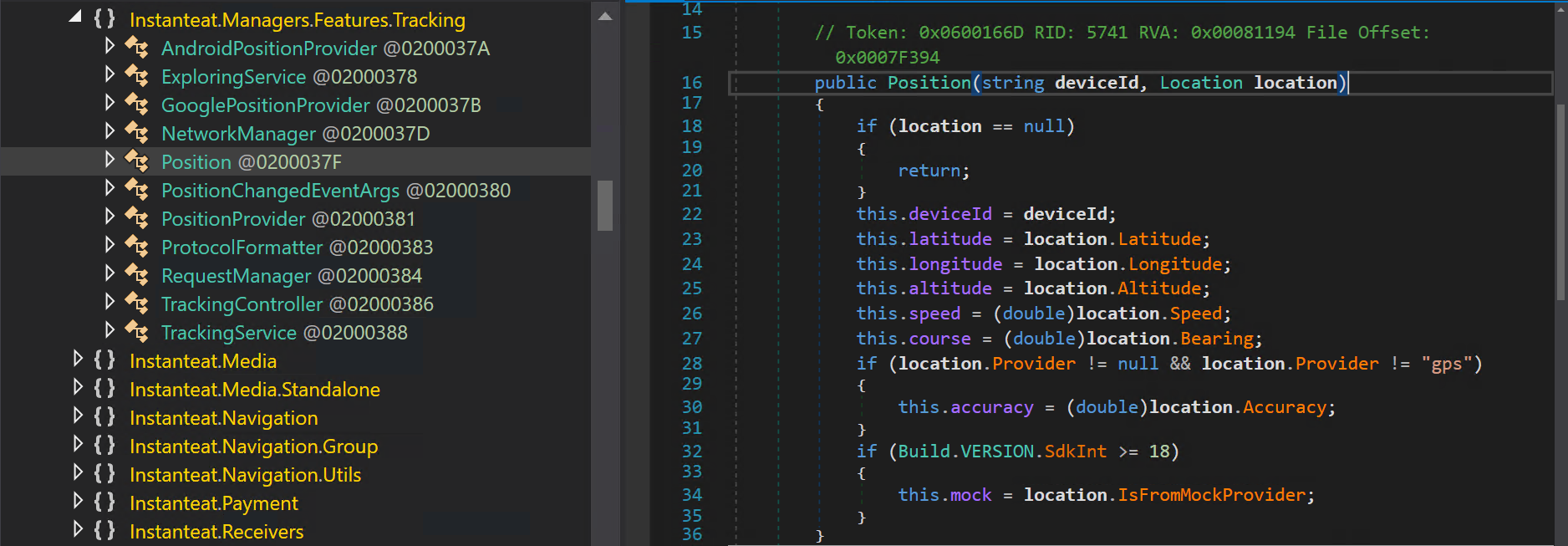
Una cosa l’app la fa bene: geolocalizzarvi e inviare la vostra posizione geografica al server.
“Tranquilli”, non lo fa in background (mentre l’applicazione è chiusa), ma lo fa ogni qual volta aprite l’app, cliccate qualsiasi cosa in giro, oppure in autonomia ogni minuto che l’app rimane aperta.
La posizione inviata al server è precisa con risoluzione di pochi metri, perché l’app la recupera dal GPS del telefono.
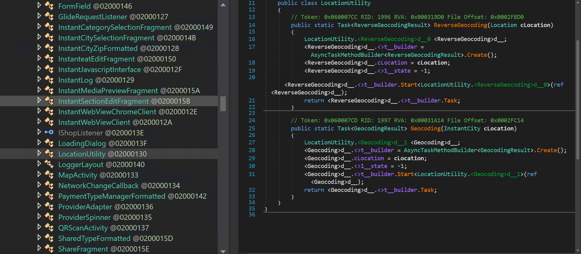
Non solo vengono inviate le coordinate latitudine, longitudine, e altitudine, ma l’applicazione usa anche un’API di Google Maps per effettuare il “reverse” e recuperare l’indirizzo (via, città, provincia). Tra l’altro effettua questa operazione “client-side”, facendo disclosure dell’API-Key utilizzata per autenticarsi a tale servizio 😳 .
Assieme ai dati di geolocalizzazione l’app invia un identificativo univoco del nostro dispositivo, il suo UserAgent, ed è predisposta ad inviare anche il nome, il modello e il numero seriale (funzionalità che pare non funzionare).
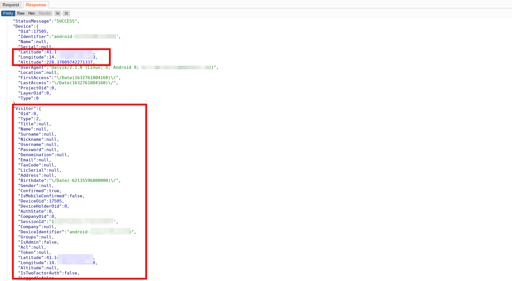
La risposta che il server invia all’app contiene i campi: nome, cognome, username, password 😳 , email, data di nascita, e codice fiscale. Al momento tali parametri sono vuoti poiché l’applicazione non prevede che l’utente si registri ed effettui un login, ma potrebbero essere disponibili in futuro.

PRIVACY POLICY
Non pervenuta. L’app e il sito non avvisano che viene raccolta la posizione geografica precisa (tramite GPS) e inoltrata ai server di Analist Group.
Certo, gli altri dati come nome, cognome, ecc, sono vuoti. C’è però l’ID univoco del dispositivo e un bel cookie di sessione (e ovviamente il nostro indirizzo IP).
Qualora l’app, anche in futuro, dovesse far funzionare le già presenti aree di registrazione e login, Analist Group sarebbe in grado di de-anonimizzare tutti i dati, anche quelli passati, inviati fino ad ora in forma pseudo-anonima >:( .
Oltre al discorso della geolocalizzazione l’app utilizza 7 tracker, di cui l’utente dovrebbe essere informato:
- AltBeacon
- Branch
- Facebook Analytics
- Facebook Login
- Facebook Places
- Facebook Share
- Google Firebase Analytics
Ci sono gli estremi per fare un esposto al Garante della privacy? Penso proprio di sì.
A questo link trovate la privacy policy linkata al sito “dilloaclemente.it”, e il suo mirror.
CONCLUSIONI
Questo post non è e non vuole essere un attacco politico a Mastella né tantomeno all’azienda Analist Group.
Frega un cazzo della campagna elettorale. Non ho amici candidati e di solito il mio voto finisce in quella percentuale insignificante tra l’1 e il 4%, quindi no, non mi paga la concorrenza!!1!1!.
Riguardo Analist Group: non li conosco, non mi sono antipatici, e non siamo in concorrenza. Non faccio app, il mio ambito è totalmente diverso.
Quello che attacco è l’uso e l’abuso delle buzzword come in questo caso “Intelligenza Artificiale”, soprattutto se lo scopo di tale utilizzo è quello di ingannare l’elettorato medio facendo leva sulla non conoscenza in merito ad argomenti complessi.
L’altra cosa antipatica è il non rispetto della privacy.
La tecnologia messa a disposizione dall’ecosistema mobile è potente. Lavorare con dati, metadati, e profilazione può sembrare “banale” visto le interfacce semplici esposte dai dispositivi e dalle librerie. Ma non lo è, perché prima di giocare con queste cose bisogna studiare, e prima ancora bisogna avere rispetto delle persone.
RIPRODUCIBILITÀ DELL’ANALISI
Il seguente post è stato scritto analizzando l’app “Mastella” versione 6.32 scaricata dal Play Store ufficiale Android.
- Nome dell’app: Mastella
- Nome del file: Mastella_6.32_apkcombo.com.apk
- SHA1: c36c5dc9d585446ddde56145f9dd2c48e907e518
- SHA256: 8f213df1e5a9f807007113ec21ca4b9fc97c20c4dddda626f00941556a1a9b5a
- Nome del package: com.analistgroup.mastella
- Versione: 6.32
Seguono i dati di firma dell’APK
Subject: C=US, ST=California, L=Mountain View, O=Google Inc., OU=Android, CN=Android
Signature Algorithm: rsassa_pkcs1v15
Valid From: 2021-06-07 14:10:21+00:00
Valid To: 2051-06-07 14:10:21+00:00
Issuer: C=US, ST=California, L=Mountain View, O=Google Inc., OU=Android, CN=Android
Serial Number: 0x22ecfd7bac07f5c9257916b3decd5fc51c93b543
Hash Algorithm: sha256
md5: 9b38cb5fccb8c773b79f6b1217bbb564
sha1: 91013bcd301c636c69d0ed4b26770c77acd1f019
sha256: 69f519287e8e0863d2a50c9f2c38c9f452531ac8b172de8c971cac4e8bf851ae
sha512: 1c61bf3359911dd71c65e9cdb072ef12bd91356f9fbe2db61baa801f88b20cf998b11ec893eafcf9f89314d8166e78f88199ae4eef6f942365b2749c87f1ccb9
PublicKey Algorithm: rsa
Bit Size: 4096
Fingerprint: 09940338e84e787c7b18cdee3610bef17f09a39f3928be3fbbe0b1389ea161c8


